14.6 100-Mbps Configuration Guidelines: Model 2

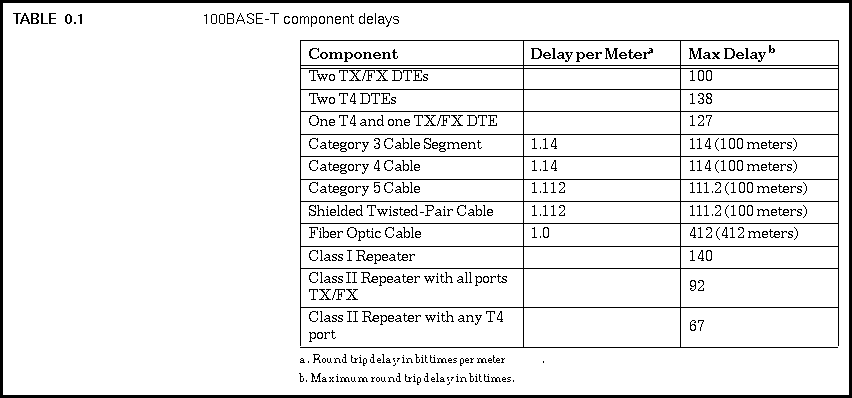
To calculate the round trip delay value for segments in the worst-case path, you multiply the length of the segment (in meters) times the "Delay per Meter" listed in the table for the segment type, which results in the round trip delay in bit times. If your segment is the maximum length, or if you're not sure of the segment length and want to use the maximum length in your calculations just to be safe, then instead of calculating the segment delay time you can use the "Max Delay" value listed in the table for that segment type.
Once you have calculated the segment delay values for each segment in the worst-case path on your LAN, you then add the segment delay values together, along with the delay values for two DTEs, and the delay for any repeaters in the path, to find the total path delay. Your vendor may provide values for cable, DTE, and repeater timing, which you can use instead of the ones in the table.
To this total you add a safety margin of from zero to four bit times, with four bit times of margin recommended in the standard. This helps account for unexpected delays, such as those caused by long patch cables between a wall jack in the office and the computer. If the result is less than or equal to 512 bit times, the path passes the test.
Generated with CERN WebMaker