Round trip delay for sample network using default timing values
14.7 Model 2 Configuration Example
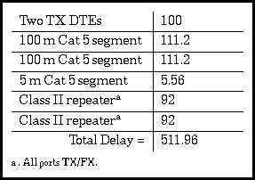
To find the delay of the 5 meter inter-repeater segment we multiply the round trip Delay per Meter for Category 5 cable (1.112) times the length of the segment in meters (5) and end up with 1.112 x 5 = 5.56 bit times for the round trip delay. Now that we know the segment round trip delay values, we can complete the evaluation by following the steps for calculating the total round trip delay for the worst-case path.
TABLE 14.5 
Round trip delay for sample network using default timing values
To calculate the total round-trip delay we use the delay times for DTEs and repeaters found in Table 14.2. As you can see, the total round trip path delay value for the sample network is 511.96 bit times when using Category 5 cable. This is less than the maximum of 512 bit times allowed, which means that the network passes the test for round-trip delay. Note, however, that there is no margin of up to 4 bit times provided in this calculation. The bit time values we used were all from Table 14.2, which provides worst-case values that you can use if you don't know what the actual cable values, repeater timing, or DTE timing is.
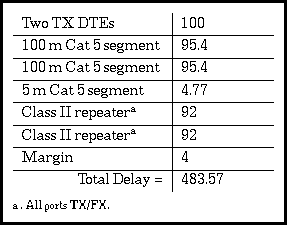
On the other hand, let's see what happens if we work this example again, using actual cable specifications provided by a vendor. Let's assume that the Category 5 cable is AT&T type 1061 cable, a non-plenum cable which has an NVP of 70% as shown in Table 14.4. If we look up that speed in Table 14.3, we find that a cable with a speed of 0.7 is rated at 0.477 bit times per meter. The round trip bit time will be twice that, or 0.954 bit times. The timing for 100 meters will therefore be 95.4 bit times, and for 5 meters it will be 4.77 bit times. Let's see how things add up using these different cable values.
TABLE 14.6 
Round trip delay for sample network using vendor timing for cable
As you can see, when real-world cable values are used instead of the worst-case default values in Table 14.2 there is enough timing left to provide for 4 bit times of margin while still meeting the goal of 512 with bit times to spare.
Generated with CERN WebMaker